When people think of electricity meters, the first thing that comes to mind is the wall-mounted meter installed by the power grid company to settle electricity bills.
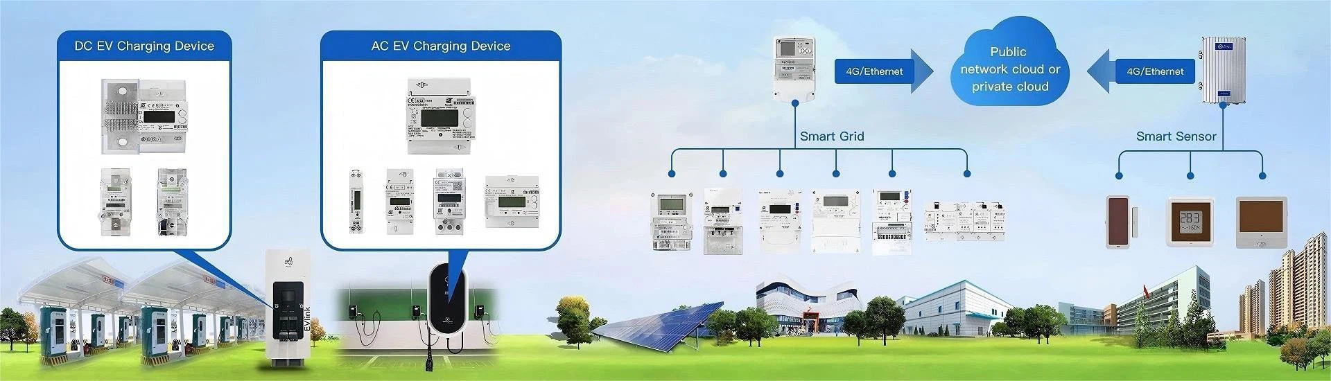
However, the applications of electricity meters extend far beyond this-they are indispensable "energy managers" in areas such as enterprise energy management, electric vehicle charging stations, photovoltaic energy storage systems, and mechanical equipment support.
So, what do electricity meters look like in these "non-grid" scenarios? And how should they be wired? This article will guide you through it all!
I. Single-Phase AC Energy Meters: The "Basic Skills" of Household Electricity Use
What is Single-Phase Electricity?
Single-phase electricity consists of one phase wire (live wire L) and one neutral wire (N), providing a single-phase sinusoidal alternating current. It is the mainstay power supply for homes, small businesses, and low-power equipment.
Standards by Country:
China: 220V / 50Hz
Europe and America: 230V / 50Hz
North America, Japan and South Korea: 100-120V / 60Hz
Wiring Principle: Regardless of the country or region, the wiring method for single-phase energy meters is largely the same. The core principle is: current coils are connected in series, and voltage coils are connected in parallel.


Key Precautions:
- Live wire must be connected to the correct terminal: Terminal 1 must be connected to the live wire.
- Current coil connected in series with the load: The current coil is connected in series with the load; the voltage coil is connected in parallel with the load.
- Same polarity principle: The two ends of both coils should be connected to the same polarity terminal of the power supply.
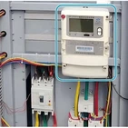
II. Three-Phase AC Energy Meters: The "Main Force" of Industrial Electricity
What is Three-Phase Electricity?
Three-phase electricity consists of three sets of alternating currents with the same frequency, equal amplitude, and a phase difference of 120°. It includes three live wires (L1, L2, L3, commonly labeled A, B, C) and one neutral wire (N). Wherein:
Line Voltage: 380V (between live wires)
Phase Voltage: 220V (between live and neutral wires)
Compared to single-phase electricity, three-phase electricity adds two phases, making the wiring naturally more complex, but the core principle remains the same.
Wiring Method:
Three-phase energy meters are available in two types: three-phase three-wire and three-phase four-wire, suitable for different load types. Depending on the load current, there are two connection methods:
Method 1: Direct Connection (Load Current ≤ Meter Range)
- Connect the three-phase live wire and neutral wire directly to the corresponding terminals on the meter.
- The meter's internal current coil is connected in series with the load, and the voltage coil is connected in parallel with the load.
- Each terminal usually has more than one fastening screw; ensure the wire ends are securely fastened during wiring.
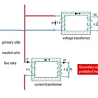
Method 2: Connection via Current Transformer (Load Current Exceeds Meter Range)
- A current transformer (CT) and a voltage transformer (PT) are required.
- The primary side of the current transformer is connected in series with the load, and the secondary side is connected in series with the meter's current coil.
- The secondary side of the current transformer must never be open-circuited.
- The primary side of the voltage transformer is connected in parallel with the load, and the secondary side is connected in parallel with the meter's voltage coil.

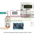
III. DC Energy Meters: The New Darling of the New Energy Era
With the rise of new energy sources, the demand for DC energy meters is increasing daily. In scenarios such as electric vehicle charging stations, photovoltaic energy storage systems, and solar DC off-grid systems, wherever DC power is supplied and electricity needs to be metered, billed, or managed, DC energy meters are required.
IV. Summary of Wiring Safety Principles (Must Read!)
Whether using AC or DC meters, the following safety principles must be kept in mind:
| Principle | Description |
|---|---|
| Current circuit in series, voltage circuit in parallel | This is the fundamental principle for wiring all electric energy meters |
| Polarity/phase sequence must be correct | Incorrect connection will lead to metering errors and even equipment damage |
| Secondary side of current transformer is strictly prohibited from open circuit | Otherwise, high voltage will be generated, endangering personal safety |
| Confirm power off before wiring | Power must be cut off before any wiring operation |
| Refer to the wiring diagram in the manual |
The arrangement of meter terminals may vary for different brands and models |
In summary
whether it's a single-phase AC meter for home use, a three-phase AC meter for factories, or a DC meter for new energy applications, although they differ in form and wiring methods, their core principle remains the same-current coils are connected in series, and voltage coils are connected in parallel.
Mastering this core principle, coupled with accurate identification of specific terminal blocks, will allow you to confidently handle meter wiring needs in various off-grid scenarios. Hopefully, this "Wiring Guide" will be a useful reference in your work!