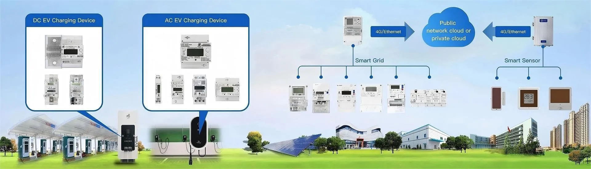


As a key component of smart grid, the reliability of single-phase smart meters has received increasing attention. Reallin used the reliability enhancement testing (RET) method for single-phase smart meters. Through historical data analysis and failure mode and effects analysis (FMEA), the main sensitive stresses and weak links affecting the reliability of single-phase smart meters were identified. Based on reliability theory and combined with the technical characteristics of State Grid's single-phase smart meters, a high-temperature reliability enhancement test scheme was designed and implemented. The test results show that this method can effectively expose the failure mode under sensitive working conditions and determine the working limit and damage limit. This study provides a reliable basis for the safety range of subsequent accelerated life tests and lays a foundation for the reliability research of smart meters.
Keywords: single-phase smart meter; reliability enhancement test; high temperature step stress test
Content
1.What is single-phase smart meter
2.Reliability enhancement test
2.1 Single-phase smart meter RET
2.2 Single-phase smart meter high temperature RET
2.2.1 High temperature step RET overview
2.2.2 Test items
3.Test result analysis
4 Conclusion
1. What Is Single-Phase Smart Meter?
2. Reliability enhancement test
The specification limit is the type of limit provided by the meter we produce. The product will be expected to work within this limit. The design limit is the limit within which the product can work properly. The difference between the design limit and the specification limit is called the design margin. The operating limit is the dividing line between normal operation and failure, under which the product will not fail and can meet the basic requirements of customers for product quality and function. Accelerated life testing is usually carried out within this limit. The destruction limit refers to the range within which the product can work without irreversible failure. Reliability enhancement testing is usually used to determine the destruction limit of the product.
RET usually adopts the method of step stress test. The type of stress can be environmental stress, such as vibration, temperature, humidity, salt spray, etc., or working stress, such as voltage, power supply, etc. During the experiment, the stress level is applied from low to high, and each stress level must be maintained for a period of time. The test will not be stopped until all the specimens fail.
2.1Single-phase smart meter RET
Weak points and sensitive stress of single-phase smart meter
Smart meter is an electric energy meter with functions such as electric energy measurement, information storage, processing exchange, network communication, real-time monitoring, and automatic control. The single-phase smart meter used in this test consists of a sampling and metering unit, a microcontroller unit (MCU), an LCD display unit, a communication unit, a power supply unit and other unit modules. The structural schematic diagram of the single-phase smart meter is shown in Figure 2. The single-phase smart meter used consists of a sampling and metering unit, a microcontroller unit (MCU), an LCD display unit, a communication unit, a power supply unit and other unit modules. The structural schematic diagram of the single-phase smart meter is shown in Figure 1.

Based on the results of historical data analysis and failure mode and effects analysis (FMEA), we found that the function of this single-phase smart meter is easily affected by temperature stress in the natural working environment. Unsuitable temperature can cause a variety of failures, such as measurement errors, indicator light failure, display abnormality, and communication interruption.
The study found that the metering unit, LCD display, and 485 communication module are the main weak links. Low temperature mainly affects the LCD display, while high temperature has a greater impact on the whole, especially the electronic components, which may cause physical changes and cumulative damage.
In summary, high temperature is identified as a key stress factor affecting the reliability of the meter. Based on these findings, we selected a single-phase smart energy meter for high temperature reliability enhancement test (RET) to further study the impact of temperature on the performance of the meter and provide a scientific basis for improving its reliability.
2.2 High-temperature RET of single-phase smart meter
The RET on the single-phase smart meter is undergoing a step temperature test, which continuously applies high-temperature step stress to the test instrument. The test will not stop until the stress level reaches the damage limit or the maximum limit of the test instrument. During the test, the key performance parameters of the smart meter are monitored in real time, and its failure mode is recorded. Then, through the analysis of the test data, its working limit and damage limit at high temperature are determined.
| Parameter Category | Parameter Name | Parameter Value | Description |
| Electrical Characteristics | Reference voltage | 220V | Standard working voltage |
| Current specification | 5(60)A | Basic current 5A, maximum 60A | |
| Accuracy level | Level 1 | Suitable for active power measurement | |
| Frequency range | (50±2.5)Hz | Applicable to standard power grid | |
| Quiescent power consumption | <1.5W,10VA | Low power consumption design | |
| Environmental adaptability | Operating temperature | -25℃~60℃ -40°℃~70°℃ |
Specification temperature range |
| Relative humidity | <95% | Extreme operating temperature | |
| Reliability | MTTF | ≥ 10 years | Mean time between failures |
2.2.1 Overview of high temperature step RET
This study only considers the influence of high temperature, and adopts the following scheme: except for the temperature parameters, other parameters are set according to the technical parameter values shown in Table 1. The normal temperature range of the smart meter is -25°C~+60°C, and the working limit range is -40°C~+70°C, so 70°C is selected as the initial temperature S1.
Considering that the recommended working limit of the chip inside the meter is usually between 80°C~85°C, the temperature step is uniformly set to 5°C, and the temperature change rate is controlled below 2.5°C/min. In order to fully observe the influence of temperature on the meter, each temperature level is maintained for 30 minutes.
Figure 3 shows the process of the step high temperature RET test. During the test, the temperature is continuously increased until all test pieces fail at a certain temperature level (t+1, i≥ 1). Then the temperature is reduced to the previous level (ti). If all test pieces can work normally at level ti, ti+1 is determined as the working limit temperature. After determining the working limit, continue testing to explore the damage limit. The method is to conduct more detailed tests in the temperature range near the working limit. For example, if the test piece cannot resume normal operation after staying at temperature tj for 30 minutes, then tj can be identified as the damage limit temperature. If the test piece can resume normal operation, continue to increase the temperature test until the maximum temperature limit of the test equipment is reached.

This method can accurately determine the working limit and damage limit of smart meters, providing key data for evaluating their high temperature reliability.
2.2.2 Test items
Based on the test instrument and test chamber capacity, 16 single-phase smart meters were selected as samples for testing. This RET includes three steps: First, an overall performance evaluation test is conducted before RET to ensure that all test pieces are qualified. Second, the online monitoring items used during RET are used to explore the changing trends of the weak links of single-phase smart meters. Finally, after RET, a comprehensive performance evaluation test is conducted at room temperature, and the test data is recorded in real time. The test items of each step are shown in Figure 4.

3. Test results analysis

Figure 5. Statistics of measurement errors at different temperature stages
| Temperature (℃) | Error range (%) | Average error (%) | LCD display | 485 communication | Overall status |
| 23 | 0.00~0.15 | 0.04 | ⭕ | ⭕ | ⭕ |
| 70 | 0.30~0.70 | 0.45 | ⭕ | ⭕ | ⭕ |
| 75 | 0.30~0.80 | 0.60 | ⭕ | ⭕ | ⭕ |
| 80 | 0.40~1.00 | 0.70 | ⭕ | ⭕ | ⭕ |
| 85 | 0.50~1.05 | 0.70 | ⭕ | △ | △ |
| 90 | 0.55~1.10 | 0.75 | △ | △ | ▲ |
| 95 | 0.60~1.15 | 0.80 | ■ | △ | ■ |
| 100 | 0.65~1.20 | 0.85 | ● | △ | ■ |
| 110 | 0.70~1.25 | 0.90 | ● | ■ | ■ |
| 120 | \ | \ | ● | ● | ● |
| 130 | \ | \ | ● | ● | ● |
| 150 | \ | \ | ● | ● | ● |
| Note:⭕Normal;△Minor impact;▲Significant impact;■Severe impact; ●Complete failure | |||||
Table 2 Relationship between RET temperature and meter performance
(1) Measurement error change: 23°C: 0.151% (maximum error value, benchmark), 70°C: 0.701% (maximum error value, significant increase), 95°C: 1.150% (maximum error value, continuous increase), 120°C: no signal (complete failure).
(2) LCD display performance: 90°C: slightly dimmed, 95°C: characters cannot be displayed, 100°C: black screen.
(3) 485 communication: 85°C: first failure, 110°C: most failures, 120°C: complete failure.
(4) Critical temperature points: 95°C: operating limit temperature (LCD large-scale failure), 120°C: comprehensive functional failure temperature, 150°C: estimated damage limit temperature.
(5) Failure process: 70°C~85°C: individual samples began to fail, 95°C: the number of failures increased significantly, 120°C: all samples completely failed.
(6) Recovery ability: When the temperature drops to 90°C, most functions are restored; when the temperature drops to room temperature, most samples return to normal.
According to the system reliability theory, the single-phase smart meter can be regarded as a series system composed of multiple unit modules. Any unit failure may cause the entire system to fail. Based on the "bathtub effect", the unit that fails first during the reliability enhancement test (RET) is the weakest part of the system. The experimental results show that the LCD display unit is the component most susceptible to temperature in the single-phase smart meter.
Based on the phenomenon that the LCD liquid crystal display disappears at 95°C and all the tested meters can be identified as failed at this temperature, we can estimate 95°C as the operating temperature limit of the single-phase smart meter. Although the online monitoring function completely fails at 120C, most of the test pieces have recovered when the temperature drops to 90°C. This RET was terminated at 150°C (the upper limit of the high and low temperature alternating damp heat test chamber). After dropping to room temperature, most of the meters passed the comprehensive performance test and resumed normal operation. It can be inferred that the damage limit temperature of the smart meter should be higher than 150°C.
The results show that the working limit of the test sample is 25K higher than the design limit, and there is a large margin between the damage limit and the working limit. This shows that the single-phase smart meter used in this RET has high reliability and can maintain stable operation in harsh environments.
4 Conclusion
Based on the RET principle and the characteristics of single-phase smart meters, a high-temperature reliability enhancement test was designed and conducted. The test verified the results of historical data analysis and FMEA, and believed that the weak links of the meter were the metering unit, LCD display unit and 485 communication unit, among which the LCD display was the weakest; the failure mode under high temperature was measured error out of tolerance, LCD display failure and 485 communication failure; the high-temperature working limit was determined to be 95°C, and the damage limit was higher than 150°C. The successful implementation of this RET not only verified the feasibility of the test plan, but also provided a basis for the parameter selection and safety range determination of the subsequent accelerated life test. At the same time, it laid the foundation for further research on reliability enhancement tests of smart meters