

Abstract : Aiming at the shortcomings of the error calibration of the electric meter b y the pulse method , a scheme of an in- telligent three-phase electric meter b y the power method calibration error was introduced. From the software and hard- ware aspects , the specific scheme of its implementation was anal yzed.
Key words : power method calibration meter ; intelligent three phase meter
Content:
4.Hardware Design Scheme
4.1 Metering Sampling Module
4.2 Human-computer interaction module
The existing error calibration design of electric meters is to accumulate the power and calibrate the error by counting the pulses emitted by the metering chip. The metering chip does not support communication to read the relevant basic data of power. This paper provides a solution for intelligent three-phase electric meters that calibrates errors by power method. The original pulse counting method is changed to the communication method to read the basic metering data to achieve error calibration.
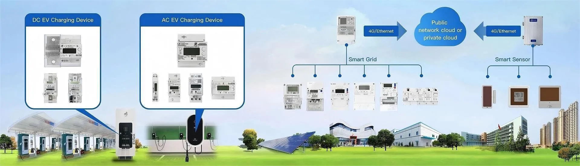
2.Overall architecture
The electric meter is composed of seven parts: measurement sampling module, human-computer interaction module, communication management module, power management module, pulse output module, storage management module, and MCU module.
3.Core chip
The power method calibration three-phase smart meter mainly includes the main control chip and the metering chip. The two types of chips exchange data through the standard 4-core interface of SPI communication.
The metering chip is a high-precision single-phase multi-function metering chip with SPI communication interface. Three 22-bit ADCs. Supports a dynamic range of 5000:1. The active power and reactive power of two metering channels can be obtained at the same time. It supports active, reactive, apparent power and electric energy pulse output, and can simultaneously obtain the effective value of three ADC channels and the frequency of the voltage channel. Supports SPI communication (including three-wire SPI communication and four-wire SPI communication) and UART communication.

The main control chip is an ultra-low power 32-bit MCU with 128kB flash memory, RTC, LCD, USB, analog functions, and 10 serial ports. The operating power supply range is 1.65 ~3.6V (without BOR) or 1.8 ~3.6V. Clock management uses a 1~24 MHz crystal oscillator, a 32kHz oscillator for a calibrated RTC, an internal 16 MHz factory-trimmed RC, an internal 37kHz low-power RC, an internal multi-speed low-power RC, a 65kHz~4.2 MHz PLL for the CPU clock and USB (48 MHz).

4.Hardware Design Scheme
4.1 Metering Sampling Module
The metering sampling module includes three-phase sampling circuit modules A, B, and C. The B-phase sampling circuit module is used as an example for specific description. The design principles of the other two modules are the same.
The B-channel sampling circuit module includes a manganese copper shunt sampling circuit and a voltage resistor voltage-dividing sampling circuit. The AD converter of the B-phase metering chip is used to sample the B-phase manganese copper loop current and the B-phase voltage respectively, and the analog differential signal is converted into a digital signal. Then, the metering data of the real-time voltage, current and power data of the B-phase is measured through the algorithm inside the metering chip. The metering chip and the main chip realize the real-time interaction of the metering data through the SPI 4-core data line channel.


4.2 Human-computer interaction module
The human-computer interaction module includes three human-computer interaction modes.
(1) The LED light flashes. Being always on is a state, and being always off is also a state. Different flashing frequencies correspond to different internal information and states of the meter.
(2) The LCD segment code displays different contents. It can display information such as power, symbols, etc.

(3) Key interaction. By pressing keys, the LCD screen can be flipped, different display contents can be switched, etc.

Aiming at the shortcomings of the traditional pulse method for meter error calibration, this paper proposes a scheme for calibrating the error of intelligent three-phase meter based on the power method, which changes the pulse counting to communication reading of basic metering data; the meter consists of seven modules including metering sampling and human-computer interaction. The core chip includes a high-precision metering chip and an ultra-low power 32-bit MCU, which communicate through the SPI interface; in terms of hardware design, the metering sampling module samples and calculates real-time data through manganese-copper shunt and voltage-dividing resistors, and the human-computer interaction module realizes information interaction and operation control in three modes: LED flashing, LCD display, and button operation.