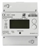
The electric meter, also known as the watt-hour meter, is a commonly used electrical instrument. Its main function is to measure the amount of electricity used. In conventional electric meters, this function is achieved by using the Lorentz force of the induced eddy current between the fixed AC magnetic field and the movable aluminum disk to drive the aluminum disk to rotate. The rotation speed of the aluminum disk is proportional to the product of voltage and current (i.e. power). The counting mechanism counts the number of revolutions of the aluminum disk to measure the consumed electrical energy.
Keywords: single chip microcomputer; smart electric meter; AD conversion; interval measurement; instantaneous measurement
Contents
This design uses a single chip microcomputer as the main control chip, collects real-time current and voltage data through current transformers and voltage transformers, and then samples and converts the analog signal into a digital signal through AD conversion, which is then processed and calculated by the single chip microcomputer to obtain the electricity and display it on the LCD screen. At the same time, the system also has data storage and communication functions. It can store power consumption data in EEPROM and transmit data with the upper system through the RS485 communication interface.
The hardware composition of the smart meter.
Current transformer and voltage transformer: This design uses precision current transformer and voltage transformer to convert the actual current and voltage into signals suitable for single-chip microcomputer processing.
AD converter: The ADC0809 chip is used to convert analog signals to digital signals, and the collected current and voltage signals are converted into digital signals that can be processed by the single-chip microcomputer.
Single-chip microcomputer: The AT89C52 single-chip microcomputer is used as the main control chip to process and calculate the collected digital signals and control the operation of the entire system.
LCD display: A 12864 liquid crystal display is used to display information such as power and system status.
EEPROM memory: The AT24C02 chip is used to store power consumption data to ensure that the data will not be lost.
RS485 communication interface: MAX3485 chip is used to realize communication with the upper system, and transmit power consumption data and system status information.
This design can not only measure the total power since installation, but also measure the interval power and instantaneous power. For the interval power and instantaneous power, the interrupt method is used for measurement, and after returning, the measured value is returned to the storage space of the total power for addition.
The following is the main program design.
Initialization program: Initialize the hardware devices such as the microcontroller, AD converter, LCD display screen, etc.
Data acquisition program: Real-time current and voltage data are collected through current transformers and voltage transformers, and the analog signal is converted into a digital signal through AD conversion. Regardless of whether the voltage signal or current signal is collected, the frequency is 50HZ. This design samples the collected power once every 0.002S, and the sampling frequency is 500HZ, which meets the requirement of "more than 5 times the frequency" of Nyquist sampling theorem. The sampling method of this design can better restore the information of the sampled power even if there is a certain frequency fluctuation.
Data processing program: The purpose is to process and calculate the collected digital signals. We set the sampling time to ts, the sampled voltage value to us, the sampled current value to is, and the energy value obtained by a single sampling is the product of the three of them, ts·us·is. Then add this value to the previous total energy value and store it in the EEPROM, thus completing the single data processing process.
Our main program is to repeatedly perform data acquisition and data processing. There are also display programs, communication programs, and exception handling programs. Their functions are as follows.
Display program: Display the information such as the power and system status to be displayed on the LCD screen. For the displayed power, it is updated every 1 second.
Communication program: Data is transmitted with the upper system through the RS485 communication interface, and the power consumption data and system status information are sent to the upper system.
Exception handling program: When the system has an abnormal situation, such as abnormal current or voltage, communication failure, etc., it can be processed accordingly and alarm prompts can be given.
The measurement of interval power is carried out by interruption. First, input the length of the interval electricity to be measured by pressing the button, such as 1 hour, 1 day. Then calculate the number of samplings required. After determining the number of samplings, start the interval electricity sampling program. Just like the main program, it also performs data acquisition and data processing. The difference is that the electricity value obtained by a single acquisition should not only be added to the previous total electricity value, but also to the total interval electricity value. After the sampling times are completed, jump out of the measurement of this interval electricity and complete the measurement of this interval electricity.
The smart meter based on the single-chip microcomputer designed in this paper can realize the function of real-time monitoring and recording of household electricity consumption. It also has data storage and communication functions. It can store electricity data in EEPROM and transmit data to the upper system through the RS485 communication interface. In the later stage, the WiFi module can also be added to communicate with the outside world. The measurement results are accurate and have good anti-noise and anti-interference capabilities. This design can improve electricity efficiency, reduce energy waste, and provide strong support for the intelligence and automation of smart home systems.


