Three-phase AC energy meters are important equipment in the power metering system. The upper limit of their measured power is not a fixed value, but is directly determined by the connection method. There are three main types: direct connection type, external current transformer (CT) type, and voltage transformer (VT) + current transformer (CT) combination type. Due to differences in structural design, adapted voltage level and load characteristics, they have different maximum power ranges and application scenarios.
This article will comprehensively analyze the core characteristics of various types of electricity meters from four dimensions: principle, calculation logic, upper limit of measurement range, and scenario adaptation.

Direct-Connection Three-Phase AC Electricity Meter
Connection Principle and Power Calculation Logic
Direct-connection electricity meters do not require additional current transformers. Current flows directly through the internal current coil, and voltage is directly connected to the internal voltage coil, making them suitable for low-voltage power distribution systems (e.g., rated voltage 380V). Their maximum power is determined by their rated current, and the core calculation formula is:
▶ Pₘₐₓ = √3 × Uₙ × Iₙₘₐₓ × cosφ
Where: Uₙ = 380V (rated line voltage of the low-voltage system), Iₙₘₐₓ is the maximum rated current of the electricity meter, and cosφ is the power factor (usually 0.8 for industrial loads and 1 for purely resistive loads).
Upper Limit of Maximum Power
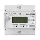
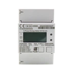
Taking the UBS direct-connection three-phase AC energy meter as an example (applicable to three-phase AC charging piles and other scenarios), its maximum rated current is commonly 0.25-5 (65) A (the value in parentheses is the maximum allowable current). Using a voltage of 380V as an example, the following calculations are made:
When cosφ=0.8, Pₘₐₓ=√3×380V×65A×0.8≈34.45kW;
When cosφ=1, Pₘₐₓ=√3×380V×65A×1≈42.9kW.
A few manufacturers offer products with a maximum allowable current of 120A, corresponding to a maximum power of approximately 79kW, but the maximum supported power of mainstream products is concentrated in the 20-70kW range.

Applicable Scenarios
Due to the elimination of the need for current transformers, ease of installation, low cost, and range adaptability to low-power loads, direct-connection energy meters are mainly used for:
- Three-phase metering in residential communities (such as villas and townhouses);
- Small commercial loads such as small shops and convenience stores;
- Low-voltage, low-power equipment in laboratories and small workshops (such as small machine tools and ventilation equipment);
- Local low-voltage distribution branch metering in office buildings.
External Current Transformer (CT) Type Three-Phase AC Energy Meter
Connection Principle and Power Calculation Logic
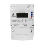
The core design of this type of energy meter is "small current metering + large current extension": the rated current of the energy meter itself is only 0.01-0.05 (6) A/1 (6) A (UBS specification), and the actual measured current is determined by the primary current of the external CT. The function of the CT is to convert the large current in the line into a small current (such as 5A) input to the energy meter according to a fixed transformation ratio. Therefore, the maximum power limit depends on the primary current specification of the CT, and the calculation formula is:
▶ Pₘₐₓ = √3 × Uₙ × I₁ × cosφ
Where: Uₙ=380V (low voltage/medium voltage low voltage side), I₁ is the maximum rated current of the primary side of the CT, and cosφ is taken as 0.8-1.
Maximum Power Limits
The primary current specifications of CTs cover a wide range, from 50A to 3000A, with corresponding maximum power increasing in a stepped manner:
- Small CT (50/5A): I₁=50A, Pₘₐₓ≈26.5kW;
- Medium CT (200/5A): I₁=200A, Pₘₐₓ≈106kW;
- Large CT (1000/5A): I₁=1000A, Pₘₐₓ≈530kW;
- Extra-large CT (3000/5A): I₁=3000A, Pₘₐₓ≈1590kW (1.59MW).
In theory, as long as the CT specifications match, this type of energy meter can support medium and high power measurements of 20kW-2MW, making it the mainstream choice for industrial scenarios.
 Type Three-Phase AC Energy Meter")
Applicable Scenarios
With the range extended by the CT, the energy meter can be adapted to medium and low voltage sides, as well as low voltage high-power loads. It is mainly used in:
- Small and medium-sized factory workshops (such as machining, textiles, and electronics manufacturing);
- Main power distribution metering in commercial complexes and office buildings;
- Branch circuits for high-power equipment such as central air conditioning and elevators in large supermarkets and hotels;
- Low-voltage power distribution systems in township substations and industrial parks.
Voltage Transformer (VT) + Current Transformer (CT) Combined Three-Phase AC Energy Meter
Connection Principle and Power Calculation Logic
This type of energy meter is specifically designed for high-voltage power distribution systems (10kV, 35kV, 110kV, etc.). It requires both VT and CT to convert the high voltage and high current to standard values that the energy meter can withstand (100V voltage, 5A current). The maximum power is determined by the system's rated voltage and the CT's primary current, calculated using the following formula:
▶ Pₘₐₓ = √3 × Uₛ × I₁ × cosφ
Where: Uₛ is the rated line voltage of the high-voltage system, I₁ is the maximum rated current on the primary side of the CT, and cosφ is taken as 0.8-1.
Maximum Power Limit
The voltage level and CT specifications of a high-voltage system determine its maximum capacity:
- 10kV system + CT 600/5A: Pₘₐₓ = √3 × 10kV × 600A × 0.8 ≈ 8.3MW;
- 35kV system + CT 1000/5A: Pₘₐₓ = √3 × 35kV × 1000A × 0.8 ≈ 48.5MW;
- 110kV system + CT 3000/5A: Pₘₐₓ = √3 × 110kV × 3000A × 0.8 ≈ 474MW.
In practical applications, the maximum supported power of this type of energy meter can extend from 5MW to over 500MW, fully covering the high-voltage, high-power metering requirements.
 + Current Transformer (CT) Combined Three-Phase AC Energy Meter")
Applicable Scenarios
As a core metering device in high-voltage power distribution systems, its applications are highly concentrated in:
- Metering of grid-connected electricity from large power plants and hydropower stations;
- Metering of main lines in regional substations and high-voltage distribution networks;
- High-voltage production lines in heavy industries such as steel, chemicals, and non-ferrous metals;
- High-voltage output metering of new energy power plants (wind power, photovoltaic).
Summary
| Connection Method | Max Supported Power Range | Core Application Scenarios | Key Selection Considerations |
|---|---|---|---|
| Direct Connection | 20-70kW | Low-voltage small loads (residential, small commercial, laboratories) | Match the rated current of the load; no additional equipment required |
| External CT Connection | 50kW-2MW | Medium and large power loads on low-voltage / medium-voltage low-side (factories, commercial complexes) | Select CT ratio according to the load current |
| VT + CT Combined Connection | 5MW-500MW+ | High-voltage ultra-high power loads (power plants, substations, heavy industry) | Match system voltage and CT ratio; meet high-voltage insulation requirements |
In short, the direct connection type wins in terms of convenience and economy, the external CT type wins in terms of flexible measurement range, and the VT+CT combination type is strong in high voltage and high power adaptation.